# ColorPatternTracker
**Repository Path**: mirrors_Samsung/ColorPatternTracker
## Basic Information
- **Project Name**: ColorPatternTracker
- **Description**: This GPU based computer vision software tracks a color-grid pattern at ~60Hz using an Android phone for effective position tracking in VR headsets.
- **Primary Language**: Unknown
- **License**: Apache-2.0
- **Default Branch**: master
- **Homepage**: None
- **GVP Project**: No
## Statistics
- **Stars**: 0
- **Forks**: 0
- **Created**: 2020-09-25
- **Last Updated**: 2026-07-05
## Categories & Tags
**Categories**: Uncategorized
**Tags**: None
## README
News:
1. The source code now uses OpenGl Compute Shader instead of OpenCL and thus works reliably on Galaxy S7. [Tested only on Galaxy S7.]
2. A further optimized C++ code for the tracker is provided in Tracker_openmp folder.
Color Pattern Tracker: User Guide
==========
This is a computer vision based real-time pattern tracking project implemented in android using GPU via OpenCL [also available on [GooglePlay](https://play.google.com/store/apps/details?id=com.samsung.dtl.colorpatterntracker)]. Here a color grid pattern printed on a regular paper pattern is tracked using a smartphone camera to estimate its position and orientation. The estimated position is then transmitted via bluetooth to any paired device, say, a VR headset.
Virtual reality, or VR, is the newest and potentially the most efficient
dimension of media. One of the important components of creating a
virtual experience is simulating the vision. And for simulating vision,
one should know the user’s field of view at any given time. The field of
view is in turn determined by the position and orientation of user’s
head. Only a few companies have provided some solutions to the head tracking
problem.
System overview
===============
Here, we describe a cost efficient solution to head tracking. It only
requires a color-printed sheet of paper and a commodity smartphone. In
the proposed system, a printed pattern is tracked using the smartphone
camera to estimate its position and orientation. The estimated position
and orientation are then sent back to the headset via bluetooth. The
headset in turn renders a virtual scene from a desired viewpoint
relative to the user’s head. High efficiency and accuracy are two of the
main characteristics of our system that makes it viable.
The main components of the proposed systems are
1. Pattern design
2. Detector/tracker design
3. Multiple pattern registration
Pattern design
--------------
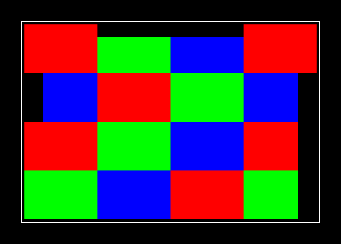
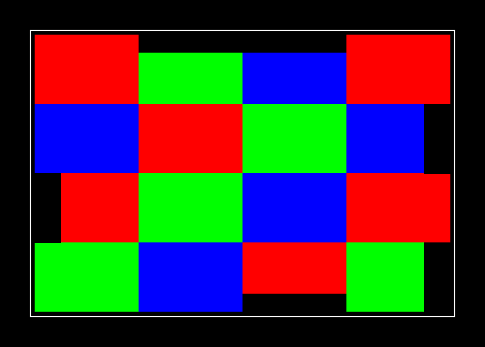
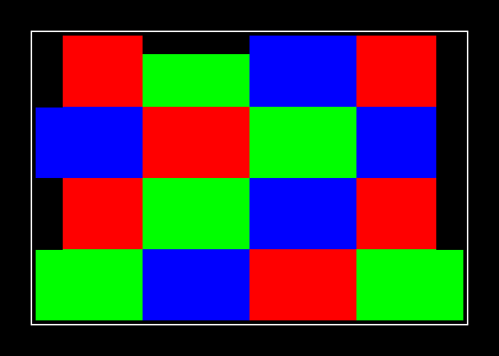
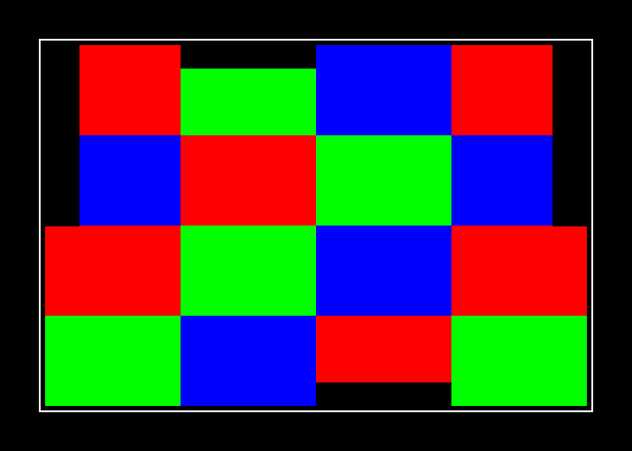
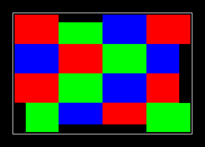
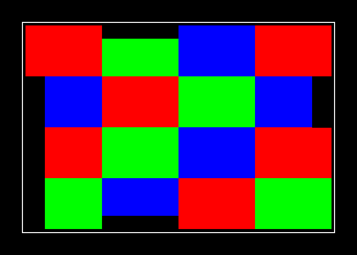
The six patterns used in our system are shown in the figure
above. Note that the only difference between the different
patterns is on their border. Different patterns have different grid
blocks with black outer border and this difference is what is used to
identify different patterns. These borders are specifically placed with
good error tolerance using error correcting codes.
The color grid pattern itself is designed by exhaustively searching for
all possible combinations of red, green and blue colors on a grid of
size 4 x 4 for quick and accurate detection.
|  |
|  |
|  |
| ------------- | ------------- | -------|
| Pattern 0 | Pattern 1 | Pattern 2|
|
|
| ------------- | ------------- | -------|
| Pattern 0 | Pattern 1 | Pattern 2|
|  |
|  |
|  |
| Pattern 3 | Pattern 4 | Pattern 5|
Detector/Tracker design
-----------------------
The pattern is detected by fast detection of corners in the image which
contain all the three colors used e.g. red, green and blue. It uses a
highly optimized coarse to fine algorithm implementation for precise
detection of corners. Note that all the 9 interior corners of the grid
pattern have all the three colors surrounding them.
We avoid running (relatively) expensive pattern detection algorithm in
each frame of video captured by the camera by predicting the position of
the corners in the next frame and then confining the search for corners
to a small region. The well known Kalman filter is also used to smoothen
the pattern trajectory.
Multiple pattern registration
-----------------------------
In order to be able to track the user’s head with a single camera,
multiple patterns are required to be placed on the headset in case one
of the patterns is highly oblique to the camera. To achieve this,
relative position and orientation of different patterns is estimated.
Detailed description
====================
A paper providing the algorithm description and theoretical underpinnings is available [here](https://drive.google.com/file/d/0B9ib55eGTbQCRmptcXNuQW1oSkk/view?usp=sharing). The doxygen documentation generated from this project is available [here](https://rawgit.com/Samsung/ColorPatternTracker/master/PatternTracker/doxygen/html/index.html).
TODO
====
Incorporate evaluation metrics.
Operation
=========
In this Section we shall describe the procedure to operate the system
with varying degree of control on the system. First we shall describe
the simplest way to run the system using the provided .apk files.
Following are the minimum set of items required to operate the proposed
system:
1. Tracker phone: Galaxy S7
2. VR headset: GearVR with a smartphone (VR phone)
3. Printed patterns: Cardboard/foamboard cutouts with patterns pasted
As more control is required on the system, additional software will be
required.
|
| Pattern 3 | Pattern 4 | Pattern 5|
Detector/Tracker design
-----------------------
The pattern is detected by fast detection of corners in the image which
contain all the three colors used e.g. red, green and blue. It uses a
highly optimized coarse to fine algorithm implementation for precise
detection of corners. Note that all the 9 interior corners of the grid
pattern have all the three colors surrounding them.
We avoid running (relatively) expensive pattern detection algorithm in
each frame of video captured by the camera by predicting the position of
the corners in the next frame and then confining the search for corners
to a small region. The well known Kalman filter is also used to smoothen
the pattern trajectory.
Multiple pattern registration
-----------------------------
In order to be able to track the user’s head with a single camera,
multiple patterns are required to be placed on the headset in case one
of the patterns is highly oblique to the camera. To achieve this,
relative position and orientation of different patterns is estimated.
Detailed description
====================
A paper providing the algorithm description and theoretical underpinnings is available [here](https://drive.google.com/file/d/0B9ib55eGTbQCRmptcXNuQW1oSkk/view?usp=sharing). The doxygen documentation generated from this project is available [here](https://rawgit.com/Samsung/ColorPatternTracker/master/PatternTracker/doxygen/html/index.html).
TODO
====
Incorporate evaluation metrics.
Operation
=========
In this Section we shall describe the procedure to operate the system
with varying degree of control on the system. First we shall describe
the simplest way to run the system using the provided .apk files.
Following are the minimum set of items required to operate the proposed
system:
1. Tracker phone: Galaxy S7
2. VR headset: GearVR with a smartphone (VR phone)
3. Printed patterns: Cardboard/foamboard cutouts with patterns pasted
As more control is required on the system, additional software will be
required.
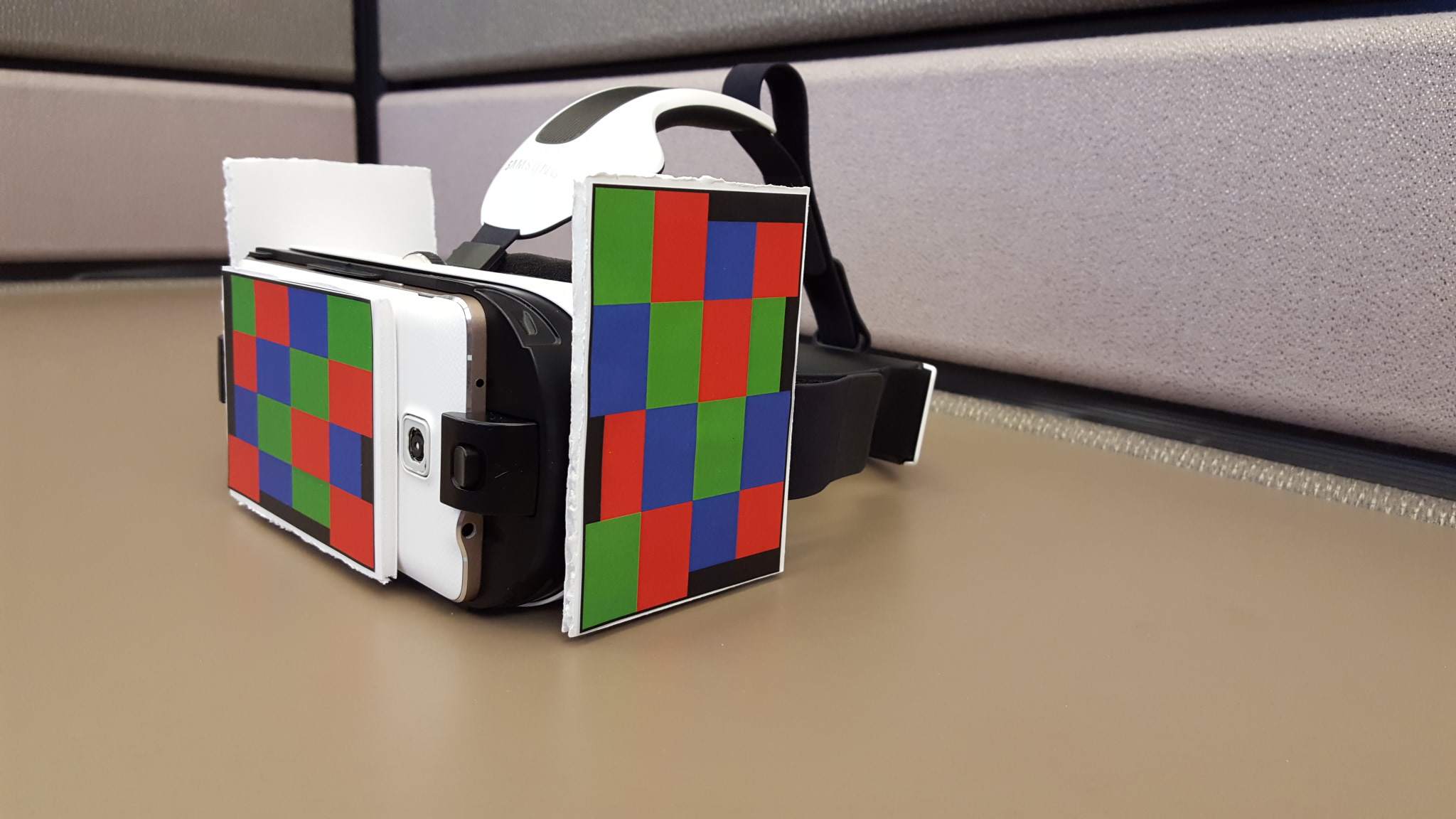 VR Headset
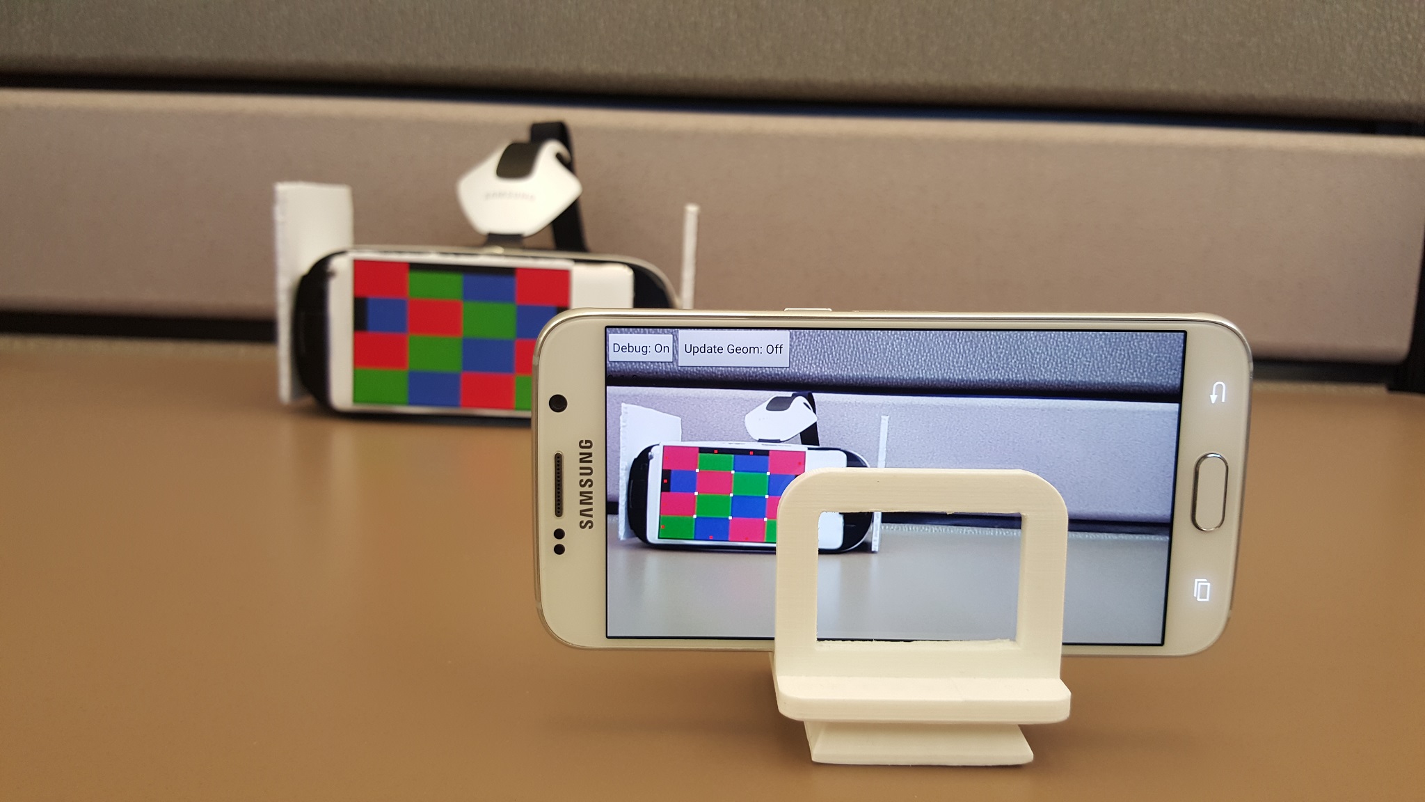 Tracker phone
Direct installation
-------------------
Following are the instructions to directly operate the system without
installation:
1. Install the Tracker apk \[PatternTracker.apk\] available in the "Executables" folder on the Tracker phone.
2. Install VR apk \[TrackerGearVR.apk\] available in the "Executables" folder on a the VR phone or compile is as described [here](GearVRScene/README.md).
2.1 Alternatively, you can try the [GearVRf](https://resources.samsungdevelopers.com/Gear_VR/020_GearVR_Framework_Project/020_Get_Started) example provided [here](GearVRf/README.md).
2.2 Or you can try the [Sketchfab](https://sketchfab.com/) example provided [here](Sketchfab/README.md)
3. Pair Tracker phone and VR phone via bluetooth.
4. Print the six patterns shown in the figure above as described
in “Pattern printing instructions" below
5. Attach the Pattern 0 on the front side of VR headset. Attach additional patterns only if you plan to register multiple patterns. See figure above.
6. Start the PatternTracker.apk on Tracker phone. Place this phone
horizontally so that the “Debug:off" button is on top left corner and
the back-facing camera facing towards the user. See Figure
above. Place it appropriately so that the
GearVR is comfortably in the field of view.
7. Start the app on the VR phone and put it in GearVR.
8. Wear GearVR and try to move back and forth, and left and right to
notice that your view in VR is adjusting according to your motion.
Tracker phone
Direct installation
-------------------
Following are the instructions to directly operate the system without
installation:
1. Install the Tracker apk \[PatternTracker.apk\] available in the "Executables" folder on the Tracker phone.
2. Install VR apk \[TrackerGearVR.apk\] available in the "Executables" folder on a the VR phone or compile is as described [here](GearVRScene/README.md).
2.1 Alternatively, you can try the [GearVRf](https://resources.samsungdevelopers.com/Gear_VR/020_GearVR_Framework_Project/020_Get_Started) example provided [here](GearVRf/README.md).
2.2 Or you can try the [Sketchfab](https://sketchfab.com/) example provided [here](Sketchfab/README.md)
3. Pair Tracker phone and VR phone via bluetooth.
4. Print the six patterns shown in the figure above as described
in “Pattern printing instructions" below
5. Attach the Pattern 0 on the front side of VR headset. Attach additional patterns only if you plan to register multiple patterns. See figure above.
6. Start the PatternTracker.apk on Tracker phone. Place this phone
horizontally so that the “Debug:off" button is on top left corner and
the back-facing camera facing towards the user. See Figure
above. Place it appropriately so that the
GearVR is comfortably in the field of view.
7. Start the app on the VR phone and put it in GearVR.
8. Wear GearVR and try to move back and forth, and left and right to
notice that your view in VR is adjusting according to your motion.
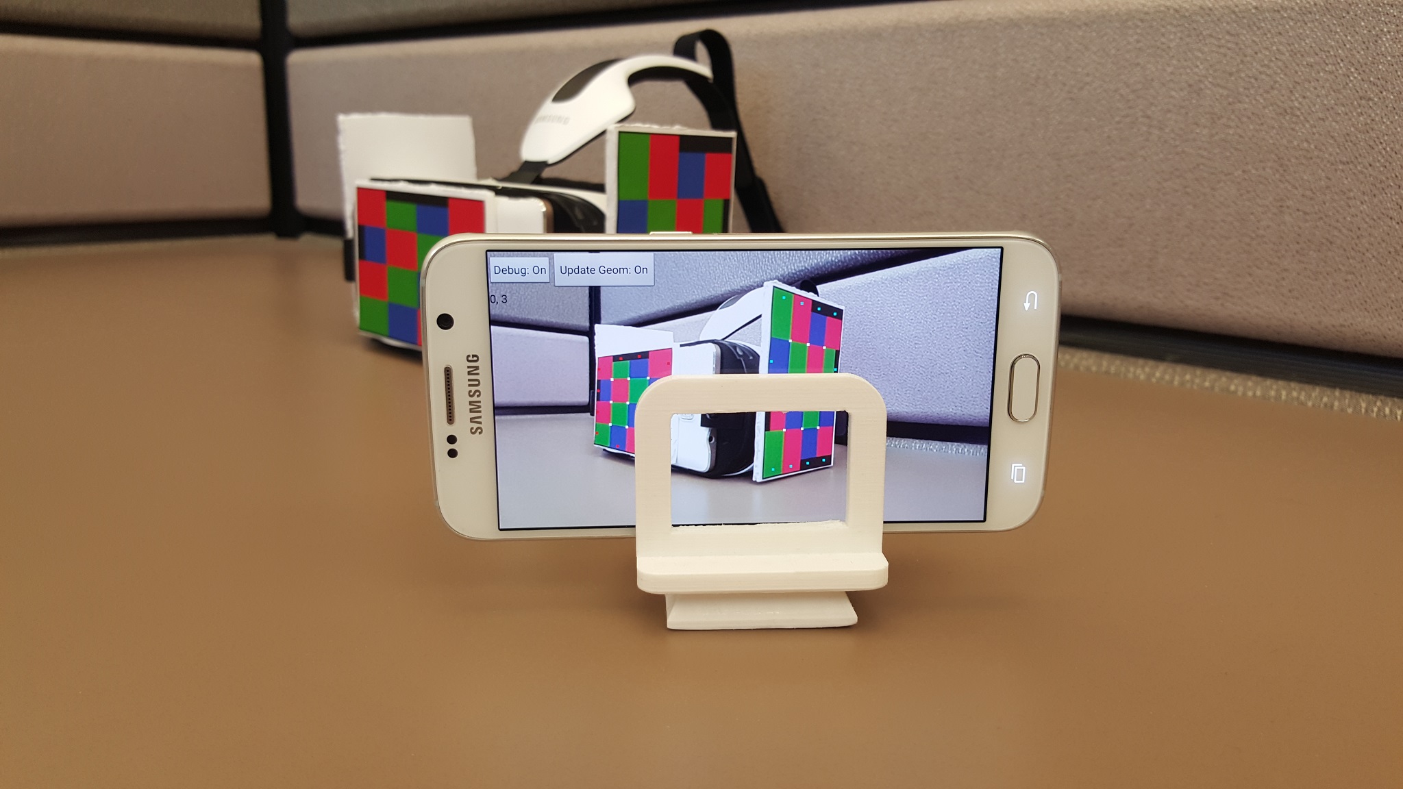 Tracker phone with “update geometry" feature on.
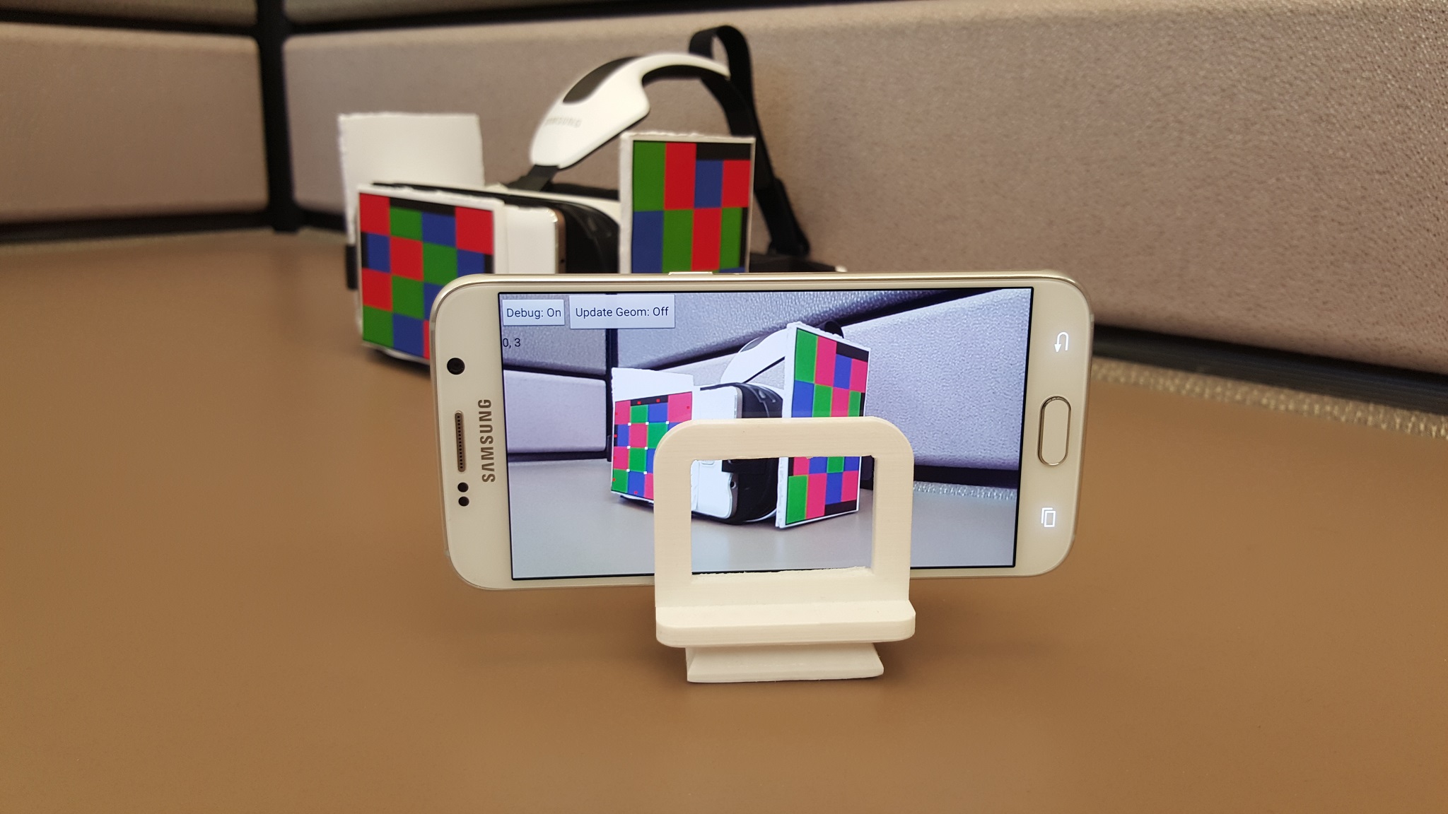 Tracker phone with “update geometry" feature off.
**Instructions for registering multiple patterns:**
0. Paste multiple patterns on the VR Phone.
1. Click the “Update Geom: off" button so that it show “Update Geom:
on"
2. Place the camera of the Tracker phone so that the Pattern 0 and one
of the other patterns are in view as seen on its screen and capture
good portion -more than half- of the screen. Make sure the lighting
is good.
3. See the corner indicators appear on the screen.
4. Once the corner indicators are stable i.e. not coming on and going
off frequently, press the “Update Geom: on” button again to turn it
into “Update Geom: off". Notice that below the buttons, each new
detected pattern will be listed. This shows that the new pattern has
been registered with the assumption that Pattern 0 was
already registered. See figure above where
Pattern 3 is registered with Pattern 0.
5. Follow steps 1 through 4 for registering each new pattern given the
already registered patterns. E.g. if in the last step Pattern 1 was
registered, in order to register Pattern 2 place the Tracker phone so
that either Pattern 0 and Pattern 2 are in view or Pattern 1 and
Pattern 2 are in view and then follow steps 2 through 3.
**Instructions for adjusting image brightness:**
1. If the image is too dark or bright, image brightness can be adjusted by clicking the "ModExp: off" button. After clicking, it will turn to "ModExp: on". See the figure for new user interface below.
2. Slide the slidebar to desired position.
3. Click the "ModExp: on" button to change it to "ModExp: off".
Tracker phone with “update geometry" feature off.
**Instructions for registering multiple patterns:**
0. Paste multiple patterns on the VR Phone.
1. Click the “Update Geom: off" button so that it show “Update Geom:
on"
2. Place the camera of the Tracker phone so that the Pattern 0 and one
of the other patterns are in view as seen on its screen and capture
good portion -more than half- of the screen. Make sure the lighting
is good.
3. See the corner indicators appear on the screen.
4. Once the corner indicators are stable i.e. not coming on and going
off frequently, press the “Update Geom: on” button again to turn it
into “Update Geom: off". Notice that below the buttons, each new
detected pattern will be listed. This shows that the new pattern has
been registered with the assumption that Pattern 0 was
already registered. See figure above where
Pattern 3 is registered with Pattern 0.
5. Follow steps 1 through 4 for registering each new pattern given the
already registered patterns. E.g. if in the last step Pattern 1 was
registered, in order to register Pattern 2 place the Tracker phone so
that either Pattern 0 and Pattern 2 are in view or Pattern 1 and
Pattern 2 are in view and then follow steps 2 through 3.
**Instructions for adjusting image brightness:**
1. If the image is too dark or bright, image brightness can be adjusted by clicking the "ModExp: off" button. After clicking, it will turn to "ModExp: on". See the figure for new user interface below.
2. Slide the slidebar to desired position.
3. Click the "ModExp: on" button to change it to "ModExp: off".
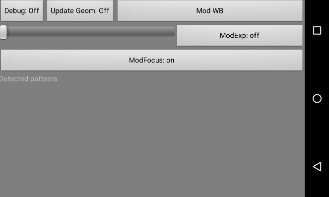 New user interface with additional controls.
**Instructions for adjusting white balance:**
1. Once the app is running and the "pattern 0" is getting tracked, press the "Mod WB" button while keeping the pattern in view. You should see the screen start changing color.
2. Wait for about 10-15 seconds while keeping the pattern in view till there is no change in screen color.
3. White balance adjust is complete. Use the phone as desired.
**Instructions for printing pattern on windows machine:**
1. Open a pattern image among those available at PatternDesign\patterns in windows photo viewer;
2. Print image in letter paper, 3.5x5in, four images in a page,
un-check “fit to frame”. Size of printed pattern should be 10.6cm
wide and 7.1cm high. See figure above.
New user interface with additional controls.
**Instructions for adjusting white balance:**
1. Once the app is running and the "pattern 0" is getting tracked, press the "Mod WB" button while keeping the pattern in view. You should see the screen start changing color.
2. Wait for about 10-15 seconds while keeping the pattern in view till there is no change in screen color.
3. White balance adjust is complete. Use the phone as desired.
**Instructions for printing pattern on windows machine:**
1. Open a pattern image among those available at PatternDesign\patterns in windows photo viewer;
2. Print image in letter paper, 3.5x5in, four images in a page,
un-check “fit to frame”. Size of printed pattern should be 10.6cm
wide and 7.1cm high. See figure above.
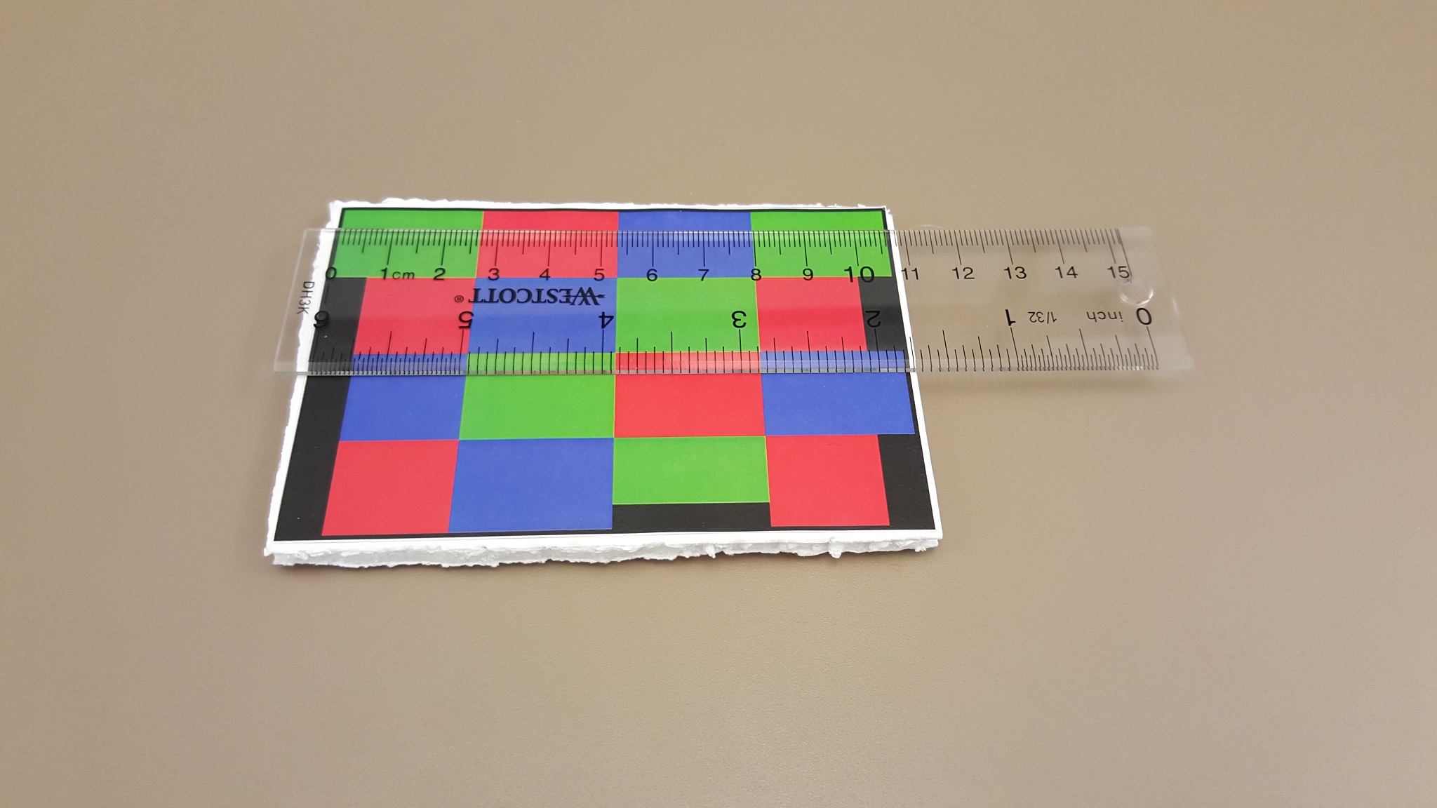 Printed pattern with a measurement scale.
In case the system crashes, one reason is that the opengl libraries on
phone are incompatible with the ones provided with the system. To
resolve this issue, the Tracker phone apk will need to be compiled again
as described in Section below.
Project compilation
-------------------
First, we shall describe the compilation of Tracker apk. The compilation
requires latest android studio with latest Android SDK and NDK, available at https://developer.android.com/studio/index.html, and OpenCV 2.4.13 for Android, available at https://sourceforge.net/projects/opencvlibrary/files/.
To compile the project,
1. Open PatternTracker folder in Android Studio using File>Open.
2. Copy the file Config\ConfigOpencv_template.mk into a new file Config\ConfigOpencv.mk .
3. Edit Config\ConfigOpencv.mk file and modify the line “include C:/.../OpenCV.mk" to provide the directory where Android OpenCV is installed.
3. Press Build>Rebuild project.
4. Connect your mobile phone and press Run> Run 'app'
It is currently tested to run on Galaxy S7 phones.
Follow the steps described in Direct Installation section to run the system.
By: Abhishek Nagar
Samsung Electronics America, Dallas
[a.nagar@samsung.com](mailto:a.nagar@samsung.com)
[https://sites.google.com/site/nagarabh/](https://sites.google.com/site/nagarabh/)
Printed pattern with a measurement scale.
In case the system crashes, one reason is that the opengl libraries on
phone are incompatible with the ones provided with the system. To
resolve this issue, the Tracker phone apk will need to be compiled again
as described in Section below.
Project compilation
-------------------
First, we shall describe the compilation of Tracker apk. The compilation
requires latest android studio with latest Android SDK and NDK, available at https://developer.android.com/studio/index.html, and OpenCV 2.4.13 for Android, available at https://sourceforge.net/projects/opencvlibrary/files/.
To compile the project,
1. Open PatternTracker folder in Android Studio using File>Open.
2. Copy the file Config\ConfigOpencv_template.mk into a new file Config\ConfigOpencv.mk .
3. Edit Config\ConfigOpencv.mk file and modify the line “include C:/.../OpenCV.mk" to provide the directory where Android OpenCV is installed.
3. Press Build>Rebuild project.
4. Connect your mobile phone and press Run> Run 'app'
It is currently tested to run on Galaxy S7 phones.
Follow the steps described in Direct Installation section to run the system.
By: Abhishek Nagar
Samsung Electronics America, Dallas
[a.nagar@samsung.com](mailto:a.nagar@samsung.com)
[https://sites.google.com/site/nagarabh/](https://sites.google.com/site/nagarabh/)